Goal and Background
The primary goal of this lab exercise was to develop our skills in various photogrammetric tasks to applied to aerial and satellite images. This lab was designed to help us comprehend the mathematics of calculating visual scale, the area and perimeters of features, and relief displacement. This lab also introduced us to the concepts of stereoscopy and orthorectification.
Methods
Part 1 - Scales, Measurements, and Relief Displacement
Part 1 of this lab was focused around calculating scale, area and perimeter measurements, and relief displacement. To calculate the scale of the aerial images we were given, the equation s = pd/gd was used where s is the scale, pd is the photo distance, and gd is the real world distance. To calculate the perimeter and area of features, the 'Measure > Polygon' and 'Measure > Polyline' digitizing tools in Erdas Imagine were used to calculate the perimeter of an object in meters and in miles and the area of the same object in acres and hectares. Finally, to calculate the relief displacement of a tall object we were given an aerial photograph, its scale, and the altitude of the sensor at the time the image was taken. Using this information the equation d = (h * r)/H was used to calculate the relief displacement. In this equation d is the displacement, h is the height of the real world object, found by using the provided scale and measuring the photo height of the object, r is the distance from the top of the object to the principal point of the image, and H is the height of the camera.
Part 2 - Stereoscopy
Part 2 of this lab was all about creating stereoscopic images using both a DEM and a LiDAR derived DSM. To do this, the 'Terrain > Anaglyph > Anaglyph Generation' tool was used in Erdas Imagine. Using the DEM and DSM as well as the provided image of the city as the inputs, the tool was run and the output images saved. These output images are Anaglyph images that can be viewed with a Stereoscope.
Part 3 - Orthorectification
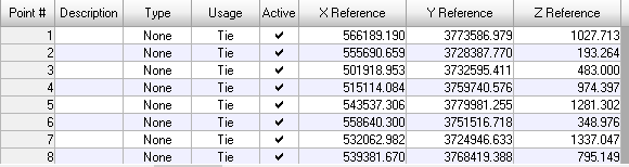
Part 3 of this lab was all about using the Erdas Imagine Lecia Photogrammetric Suite (LPS) for triangulation and orthorectification. Using the images provided by the professor, I first created a new Photgrammetric Project, added in the necessary images, and specified the sensor to correct the Interior Orientation. Next, to correct the image horizontally, I used the 'Classic Point Measurement' Tool to add GCP's to the image I was working on orthorectifying from a reference orthorectified image provided by the professor. Once eleven GCP's were added to the first image, I repeated steps for creating GCP's with a second image to correct the image vertically. Once all teh GCP's were collected for both reference images and corrected both horizontally and vertically, I ran the 'Automatic Tie Point Generation Properties' tool to collect 40 tie points. Finally, the 'Start Ortho Resampling Process' tool from IMAGINE Photogrammetry Interface could be run. In the 'Ortho Resampling' Dialog, I added the images to the correct inputs and ran the tool. Once the tool was finished running, the output images were properly orthorectified.
Results


Sources
National Agriculture Imagery Program
(NAIP) images are from United States Department of Agriculture, 2005
Digital Elevation Model (DEM) for
Eau Claire, WI is from United States Department of Agriculture Natural Resources Conservation Service, 2010.
Lidar-derived surface model (DSM) for
sections of Eau Claire and Chippewa are from Eau
Claire County and Chippewa County
governments respectively.
Spot satellite images are from Erdas Imagine, 2009.
Digital elevation model (DEM) for
Palm Spring, CA is from Erdas Imagine, 2009
National Aerial Photography Program (NAPP) 2 meter images are from Erdas Imagine, 2009.
No comments:
Post a Comment