Goal and Background
The goal of this particular lab was to introduce us to the very important remote sensing concept of geometric correction of remotely sensed images. This lab was set up so that we would gain experience with the two major forms of geometric correction, image-to-map rectification and image-to-image registration, and understand the processes of implementing one over the other.
Methods
Part 1
First, open Erdas Imagine with two separate viewers and put the provided distorted image in one viewer and the provided reference map in the other viewer. Make sure that the viewer with the distorted image is selected and then click on the Multispectral tab under the raster options and select the Control Points tool. This will open the Set Geometric Model dialog where you will scroll down and select the option of Polynomial and click OK. Hitting OK will open up two new tools, the Multipoint Geometric Correction tool and the GCP Tool Reference Setup tool. On the latter tool, accept the default option Image Layer (New Viewer) and click OK. Next, navigate to the folder that contains your images and add the reference image and click OK on the Reference Map Information dialog that pops up. This will then open the Polynomial Model Properties (No File) dialog and accept the default settings by clicking Close. Next, in the Multipoint Geometric Correction Window, remove any GCP's that were present in the image to begin with and begin adding your own. Click on the Create GCP tool and add GCP's in similar locations spread evenly across the image to both the reference image and the distorted image for only the first three GCP's. As this is a first order polynomial transformation only three GCP's are needed for the model solution to be considered current but it is always recommended to collect more than the minimum amount of GCP's. For the fourth GCP, simply add one to one image and the matching GCP will be added to the other image automatically. Next, you must reduce the Root Mean Square (RMS) Error to below 2.0 or less, though 0.5 or less is the standard but as this is the first time doing this, 2.0 is more achievable for learning purposes. Zoom in to the GCP's and move them around on the distorted and reference images until they match up and the RMS Error is within allowable limits. Once this is done, run the Display Resample Image Dialog and save the output image to the appropriate location and let the too run, dismissing it once it is finished. You should now have a new geometrically corrected image.
Part 2
For part 2, open Erdas Imagine and bring in the distorted and reference images in the same way you did for part 1. Next, click on the Control Points button under the Multispectral tab as you did in part 1 and once again select Polynomial under the Set Geometric Model dialog and click OK on the GCP Tool Reference Setup tool. Import your reference image and then click OK on the Reference Map Information dialog. On the Polynomial Model Properties dialog change the Polynomial Order from 1 to 3 and click Close. Next, click on the Create GCP tool and add in 9 GCP's to both images in a similar location and then add 3 more to just one of the images in a similar way to what was done in part 1. Move the GCP's around until you get an RMS Error of below 1.0 in this case and once this is achieved, run the Display Resample Image Dialog and save the output image in the necessary folder. Make sure to change the Resampling Method to Bilinear Interpolation under the Resample Image Window and keep all of the other default settings and then click OK to run the tool. After the tool is completed, you will have a geometrically corrected image using a third order polynomial with bilinear interpolation.
Results
Part 1 Multipoint Geometric Correction Window with 4 GCP's and an RMS error of .9721
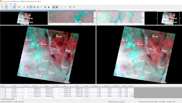
Part 2 Multipoint Geometric Correction Window with 12 GCP's and an RMS error of .1701
Sources
Satellite images are from Earth Resources Observation and Science Center, United States Geological Survey.
Digital raster graphic (DRG) is from Illinois Geospatial Data Clearing House.


No comments:
Post a Comment